
It's been too long since Naval Gazing covered fire control. As such, I'm going to start looking at the details of various portions of the fire-control process, starting with the rangefinders.
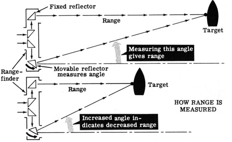
In the early days of naval fire control, many different solutions were proposed for the problem of finding range. All optical rangefinders operate on essentially the same principle, that you can construct a triangle, and knowing one side (the baseline) and some angles, use basic trigonometry to work out the other sides, one of which is the desired range.
Possibly the earliest proposal was the stadiometric rangefinder. This uses some portion of the enemy ship, usually the height of the masts, as a baseline, and measures how large of an angle it covers.1 The main advantage of a stadiometer is that it's small, cheap, and easy to make. The drawback is that it relies entirely on correct identification of the target and knowledge of the relevant baseline. For this reason, stadiometers are usually only used on submarine periscopes, which cannot fit a more sophisticated system.
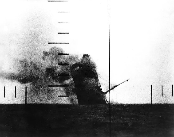
A Japanese cargo ship sinking seen through a submarine's periscope. The marks of the stadiometer are clearly visible.
The next attempt was to use the length of the firing ship as a baseline, with one observer at each end. This was good for theoretical accuracy, but had two major drawbacks. First, it relied on good communication between the two observers. If, as often happened, they were looking at different targets, the resulting range would be gibberish. Even if they were looking at the same ship, the technology of the day made it difficult to pass accurate angles quickly and ensure that they were taken at the same time. Second, the baseline grew shorter as a target moved away from the beam and towards the bow or stern, limiting accuracy.
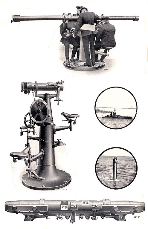
The mechanism of a basic coincidence rangefinder
The problem was eventually solved by a pair of British professors, Archibald Barr and William Stroud, and put into production by their company, Barr and Stroud. They developed a system which could be operated by one man, and didn't require knowledge of the target's size. This system was essentially a pair of periscopes mounted horizontally, and the image from each being combined in the eyepiece, with one half in the top and the other half in the bottom. The operator would tilt the mirror in one end of the rangefinder to line up a vertical feature on the target, like a mast.2 The resulting tilt allowed the triangle to be calculated, with the distance between the two mirrors serving as a baseline.
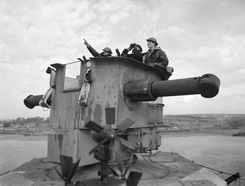
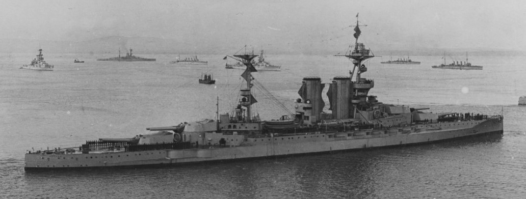
Rangefinder aboard HMS Revenge
The rangefinder was the first truly precision instrument taken to sea, and its introduction was not entirely free of trouble. Barr and Stroud discovered that a major cause of error was that their tube was insufficiently rigid, particularly in the face of temperature fluctuation. To solve this, a bar of material with a low thermal expansion coefficient was fitted inside the tube, and the mirrors were replaced by pentaprisms. However, pentaprisms always reflect light by 90°, which means they can't be tilted to align the images.
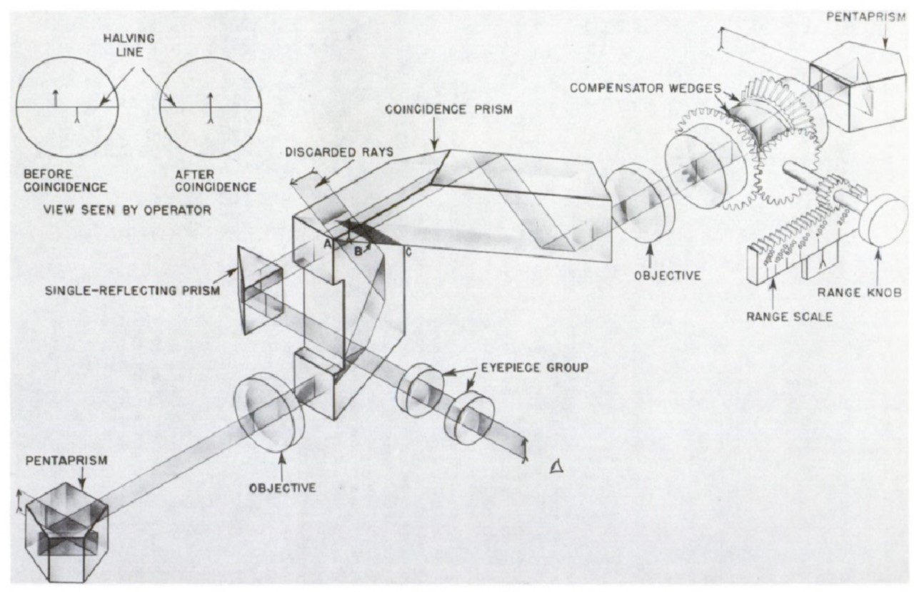
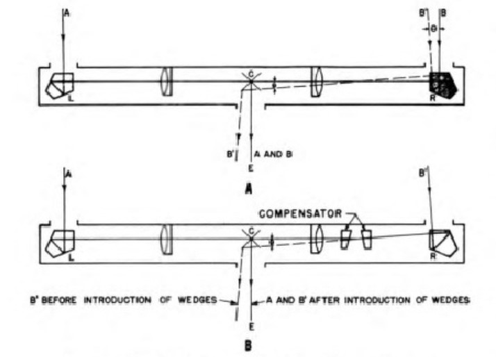
A coincidence rangefinder mechanism
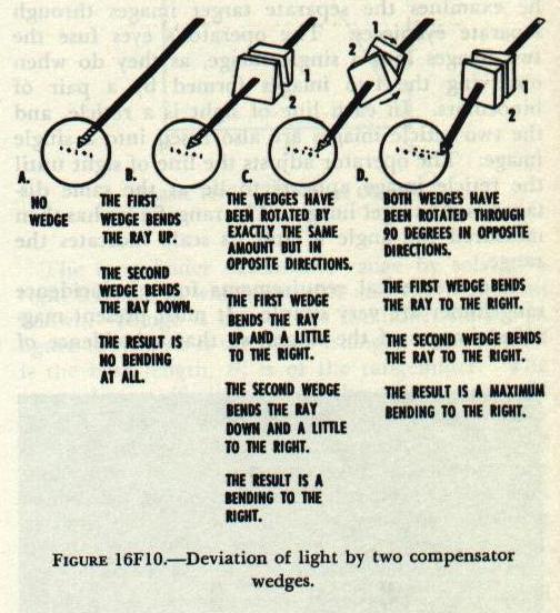
The workaround for this was fitting a pair of compensator wedges. These are identical prisms which bend the light passing through them by a certain amount. When the thick end of one is lined up with the thin end of the other, the deviations cancel each other out, except for a tiny line offset that can be ignored in practice. When the thick and thin ends are lined up, the total deviation is twice that of the single wedge. They are set up in a mechanism which rotates them in opposite directions, which cancels deviations out of the plane of triangulation, while allowing the deviations in the plane to alter the triangle. Usually, the neutral point (infinity range) was set up at one extreme, while the shortest range the rangefinder could measure was set up at the other. This gave considerably greater measurement accuracy than simply tilting a mirror, as the compensator wedges rotated through 180° in the process of changing the optical angle by less than a degree,3 while a tilting mirror would have had to tilt by only half of the change in optical angle. This makes it much easier to achieve the necessary precision with the compensators.
An alternate method, known as stereoscopic rangefinding, was developed by Zeiss in Germany. This involved the operator looking at a pair of eyepieces, one for each end of the rangefinder, and the images appearing as a 3D one to him. A pointer was optically placed in the image, and the operator adjusted it with a compensator wedge system until it was "on top" of the target. The human brain is very good at sorting out the order of objects, so this works well.
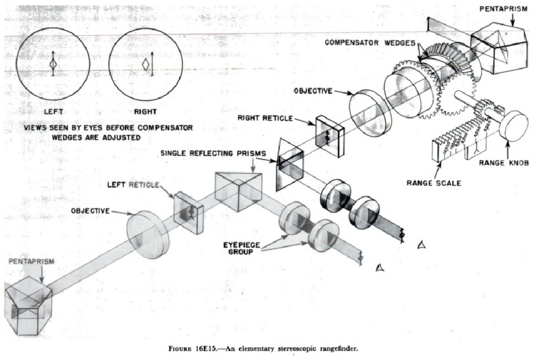
Stereoscopic Rangefinder Mechanism
Which rangefinder system is superior remains a matter of controversy to this day. The Germans immediately adopted the stereoscopic rangefinder, while the British and most other navies went with the coincidence system. The biggest advantage of the stereoscopic system is that it allows ranging on objects without a strong vertical element, such as shell splashes and airplanes. It was also generally considered more sensitive in bad lighting and areas of low contrast. However, it did require operators with perfect binocular vision, which the British claimed made it difficult to man them. They also claimed that stereoscopic rangefinders were fatiguing to use.
Barham fitted with triangular canvas baffles to thwart coincidence rangefinders by breaking up the vertical lines. Unfortunately, the German stereoscopic rangefinders were unaffected.
As best I can tell, the claims are entirely baseless. The US adopted the stereoscopic rangefinder in the interwar years, and never had any issues finding sufficient personnel. On the difficulty of use, a US report summarized the results of US research by stating "Indeed, the general conclusion to be drawn from the experiments outlined in this chapter of the present report is that stereoscopic range finding is curiously, and gratifyingly, resistant to psycho-physiological changes in the operator. This is true for fatigue, loss of sleep, drugs such as metrazol, oxygen deprivation, and postural changes."
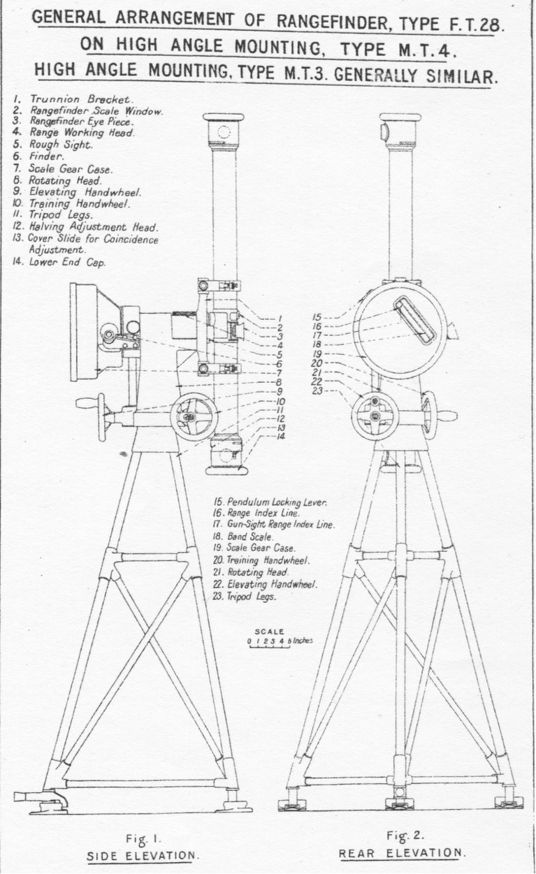
RN vertical high-angle coincidence rangefinder
The RN was the only navy not to accept the superiority of the stereoscopic rangefinder by the start of WWII. I'm not entirely certain why they didn't, but it almost looks like there was a concerted propaganda campaign against stereoscopic rangefinders by the British in the 20s and 30s. They believed the coincidence type to be so superior that they used vertically-mounted units for rangefinding on airplanes.4 This was a silly idea, and they later switched to stereoscopic for that role, but retained coincidence units for surface fire control.
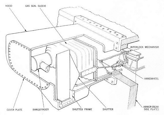
Diagram of one end of the turret rangefinder
Iowa was constructed with a total of 9 rangefinders aboard: 2 26' 6" baseline Mk 48 stereoscopic rangefinders in the Mk 38 main battery directors,5 4 15' Mk 42 stereoscopic units for the Mk 37 secondary battery directors, 2 46' Mk 52 stereo rangefinders in Turrets II and III, and a single 46' Mk 53 coincidence rangefinder in Turret I. I'm not totally sure why this was fitted, but all of my references mention the astigmatizing lens, which allowed ranging on points of light at night by stretching them into streaks.6 However, its location in Turret I proved to be easily washed out by spray, and it was removed when the ship was reactivated to go to Korea.
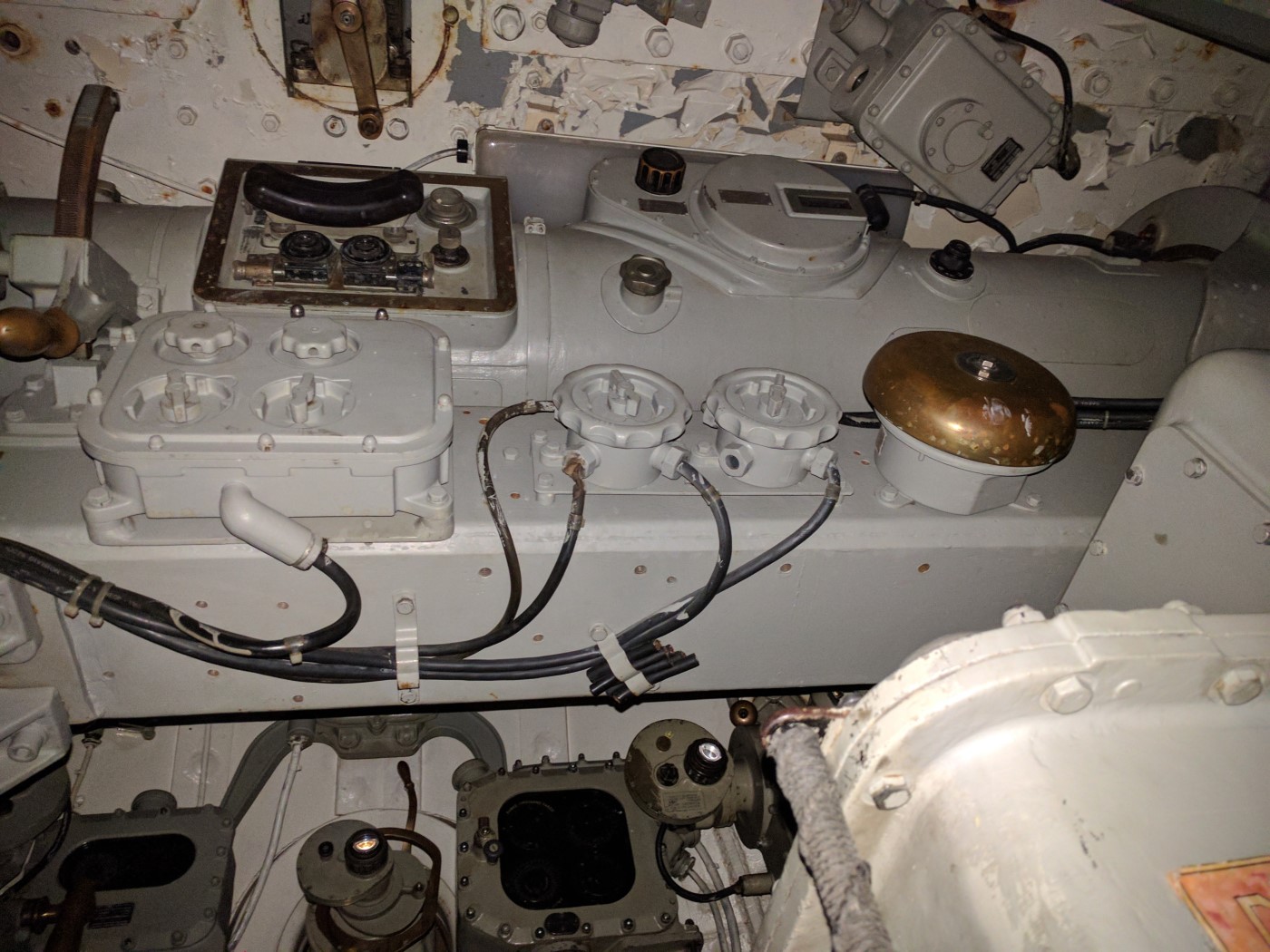
The interior of Iowa's forward Mk 38 director, including rangefinder eyepieces (top left)7
The development of radar made the optical rangefinder obsolete. Radar was more accurate, worked at night and in bad weather, and could be made considerably smaller than a long-base rangefinder. While the optical systems remained aboard, the radar quickly became the preferred source of range data. The passive optical rangefinder is essentially dead in military service today, replaced by radar and more recently laser ranges.
The optical rangefinder is a fascinating case of cleverness in action, the sort of that pervades all technology if you look deep enough. And the ranges it produces are form the first link the a chain of systems that allowed the big guns amazing accuracy. The next link was to keep track of the range as it changed, and we'll examine it next time.
1 Some stadiometers rely on the ship's length instead, although this is obviously made more complicated by the fact that the ship may not be broadside-on. There have been devices to measure this angle and compensate for it, but a longer baseline is generally better than a shorter one, so they suffer badly when the target is presenting bow or stern. ⇑
2 Only one side was adjusted because this gave greater accuracy than manipulating both sides. ⇑
3 Even on the Mk 38's rangefinder in the Iowa-class, a 1° angle would result in a range of only 1518', which is almost certainly well under the minimum range. ⇑
4 Most airplanes don't have a sharp vertical line, but they do have a horizontal line in the form of the wings/fuselage. ⇑
5 It's also supposedly possible to use the sight telescopes on the Mk 38 as an improvised rangefinder with a short baseline, although this is very much not the recommended mode of operations. ⇑
6 I think that an illuminated pointer should allow a stereoscopic rangefinder to range on points of light, but I'm not sure of that. ⇑
7 My photo. ⇑
Comments
I can't quite follow the optical mechanics of how the compensator rotation changes the effective rotation angle of the image (that is, the angle measured off the baseline...) Wikipedia doesn't even try to explain. Got a better explanation anywhere?
Also, Bean knows this as he recommended the book, but for any of you who haven't read it, Thunder Below contains a long, detailed, and interesting discussion of the use of a stadiometric rangefinder in practice. (The captain and mate discuss identifying details of a ship seen in the periscope and try to figure out which ship in their tables matches it, so they can know its mast height.)
Thunder Below is indeed excellent. I'm going to discuss it at some point. And I've added an image of compensator wedges. See here for a more detailed account.
Thanks, with that diagram it's actually crystal clear (without any prismatic effects, even :P)
Regarding radar and laser rangefinders, both of those have the disadvantage of warning a properly-equipped enemy that he is about to be shot at and from what direction. Also, potentially vulnerable to jamming. I'm actually surprised that warships in particular, which aren't as volumetrically constrained as e.g. tanks and airplanes, don't have backup optical rangefinders.
I would hope there is at least a stadiometric reticle available for the optical director, which would be a reasonable compromise.
I suspect the problem is that optical rangefinders simply aren't good enough to justify that. Sure, lasering may alert your target, but so does a shell landing nearby. And your time to the first round actually hitting is probably shorter with the laser rangefinder. Laser detectors aren't that accurate either. The last time I looked, the manufacturer was claiming 7.5 degrees, and I'd be skeptical of seeing that in reality.
A former co-worker several jobs ago used to keep an optical range-finder in his cubical. At first I thought it was a small rocket launcher. IIRC it was a German model designed for spotting artillery and so was small and man-portable.
Using it was easy - the field of view was split horizontally. The bottom half of the view looked normal. The top half was displayed upside-down. As you rotated the distance knob, the top would slide left-right. You would adjust the distance knob until features of your target lined up vertically. I think it had a max distance of around 1,500m or something.
Yep. That's a coincidence rangefinder. I didn't mention it in the post, but Iowa has (or had) a very similar model mounted on the 01 level near Turret 2. I would sometimes point out that it was the only coincidence rangefinder on the ship.
"The RN was the only navy not to accept the superiority of the coincidence rangefinder by the start of WWII."
Was that meant to be stereoscopic?
You're correct. Fixed. Can't believe that lasted this long.
@Garrett
I did a bit more looking, and found out that the inverted coincidence system is one that is apparently common for land-based rangefinders, but that isn't used at sea. I'm not sure why this is, but my first guess is that it doesn't deal well with the ship's motion.
Trying to research the main battery and secondary battery directors in the USS Texas. Texas had a Mk.XX, Mod 1 main battery director, and a Mk.VI director for the 5” guns.
Friedman’s book “Gunnery in the Age of Dreadnoughts” mention Texas had a 12’ base optical coincident rangefinder. He says this adding that there were plans to replace that with a 12’ base stereo-optic rangefinder, but doubted the work was done.
Wondering if you have a clue where this 12’ base rangefinder was located on the Texas. I had thought it was coupled / part of the Mk.XX Director, but the little cupola measures out (on 1/192nd scale plans) at exactly 12 feet. I assume the 12’ base means the optical tubes spanned 12 feet? Too tight I believe. The 12’ base rangefinder may be a piece of gear removed in her last rebuild prior to WWII…. ANY INSIGHT?
That's early enough that rangefinders might well simply be mounted by themselves in the open, and Texas had what looks like maybe two on top of turrets 2 and 4. (Someone had thought of the idea that inside the turret would be less vulnerable, but that implies making them longer, and I don't know whether it would have been possible at that time to make one that long sufficiently rigid.) These appear to have been removed later.
Putting the director (sights), rangefinder and spotting position on one mount became standard only later, after it was found (possibly at Jutland) that if they were separate, they were too likely to aim at different enemies and hit neither.
I think Friedman's US Naval Weapons has a list of the director types, and sometimes pictures.
Looking through my copy of Naval Firepower, I don't think the 12' rangefinder was coupled to the Mk XX director. Based on the caption of the picture of Nevada in the introduction, it looks like range data for the main battery director came from the rangefinders on top of the superfiring turrets. Texas doesn't seem to have carried the same fit, but besides the rangefinders on top of the turrets, there was also the one on the bridge. I'd guess that's where the data was coming from.
Beyond that, don't have much to add to muddywaters, and would suggest contacting Texas directly. They'll likely have someone on staff who knows. (Unless you're supposed to be that person, in which case, sorry, I have no idea.)