
Last time, I talked about the origins of naval fire control, and the basic problems that fire control systems have to solve. The fire control systems on Iowa are recognizable as descendants of the early systems, solving the same problems, but in a much more integrated and sophisticated way.
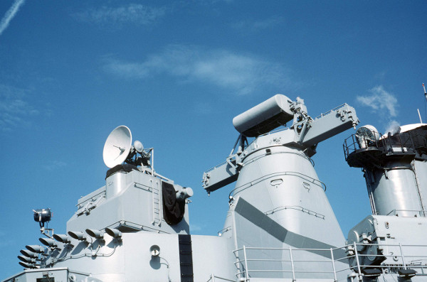
Left to right: Mk 37 Secondary Battery Director, Mk 38 Main Battery Director, Aft Stack
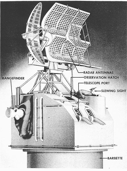
Iowa’s two main battery directors, designated Mk 38, each have an integrated rangefinder1 with a 26.5 ft base and are fully capable of providing level, cross-level, target range, target bearing, and estimates of target course and speed. This data is sent to the plotting rooms via devices called synchros. The synchro is a special type of electric motor, in which what happens on one end is mirrored exactly on the other. This is helpful as the synchro is continuous and more precise than the step-by-step motor. Most importantly, though, it is self-aligning, allowing recovery from power outages and quick switching of inputs and outputs.
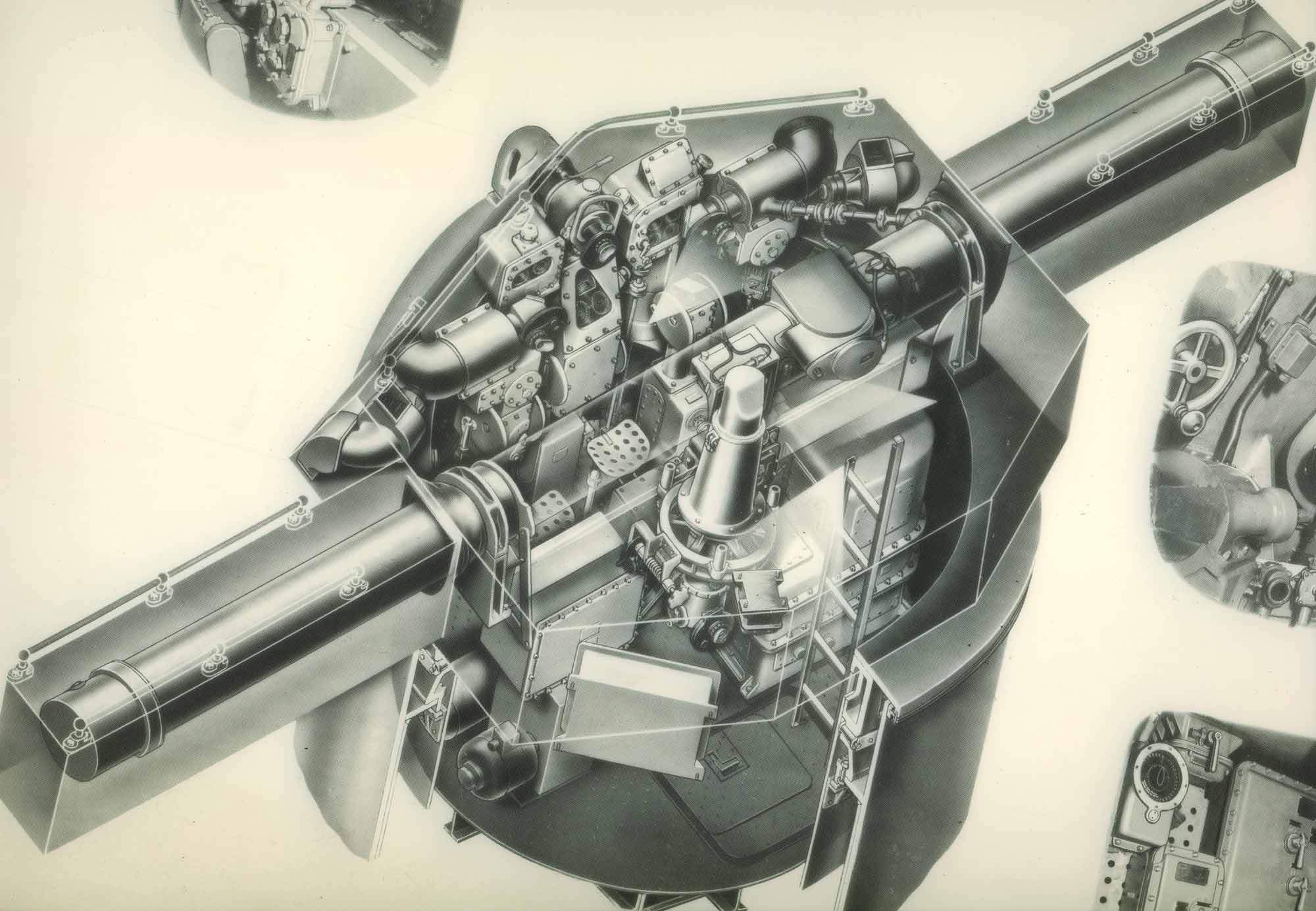
A diagram of a Mk 38 director.
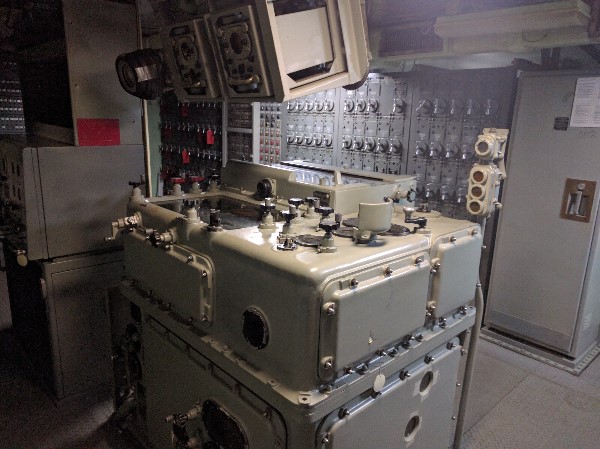
Each plotting room contains two main devices, the Mk 8 rangekeeper and the Mk 41 stable vertical. The Mk 41 is a specialized gyroscope that is the preferred source of level and cross-level data for the ship. It is more accurate than the Mk 38, and does not have to see the horizon to function. Interestingly, it is designated in the director number sequence, and is considered a director in the ship’s fire control schematics.
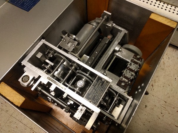
The Mk 8 is a fully mechanical fire-control computer, a distant descendant of the mechanisms first used to find range rate. The target data from the director is combined with data on the ship’s course and speed to create a virtual model of the engagement. The relative bearing and range to the target are tracked in real time, giving a constant estimate of the latest range rate. Iowa’s own movement is fully compensated for, allowing the ship to maneuver while still engaging the enemy effectively.3 The director also has the appropriate ballistic cams to deal with the final range to the target. Manual inputs for air density, average muzzle velocity, and wind speed and direction allowed those factors to be taken into account as well. In the past I’ve claimed that the system included compensation for things such as the Coriolis effect and the Magnus effect. It appears that this is not quite the case. There is a compensation for overall drift, but I’m not sure how this is calculated, or if it’s simply empirical. I don’t have a copy of the Mk 8 manual, which is probably the only place the full logic is laid out.
The gun orders are passed from the rangekeeper to the turrets themselves, where the last pieces are put into place. Mechanisms in each turret compensate for parallax (the offset between the turret and the fire-control reference point, usually the conning tower) to ensure that all of the shells land in the same place instead of producing a 400 ft pattern, as well as for barrel wear in each gun (which reduces muzzle velocity) and for any misalignment of the turret roller path with the ship’s level. The turret itself can be operated in follow-the-pointer mode, although the US was the first to introduce a successful Remote Power Control (RPC) system. RPC involves replacing the guy matching pointers with a set of synchros and servos that automatically drives the gun to point where the orders tell it to. While this sounds simple today, it was at the cutting edge of contemporary technology, and gave the US a major advantage in gunnery.
The guns themselves could be fired from inside the turret, or, more commonly, from a pair of triggers on the stable vertical. There were two different modes, and two different methods of firing. In normal weather, the stable vertical sent both level and cross-level continually to the rangekeeper, and the guns constantly moved to match it. If the ship was moving too much for the guns to keep up, selected level (or cross-level) was used instead. No attempt was made to compensate for the other axis, and a constant value, representing about the midpoint of the movement, was sent to the rangekeeper. When the ship rolled into the correct position, a contact on the gyro met another on the frame of the stable vertical. If the automatic firing key was pressed at that time, it completed a circuit and fired the guns.
Even with all of this sophistication, spotting was still necessary. However, another development greatly simplified cross-checking the solution against the real-world. Not only did the turrets have RPC, but the director did as well. The rangekeeper kept it pointed at where it thought the target was, and if the target moved out of the crosshairs, this meant the solution was off. The crew would bring it back on target, updating the rangekeeper’s solution in the process. The result? A closed-loop control system, running on late 30s analog technology. As an example of how good this system was, during the bombardment of Ponape Atoll in 1944, Iowa was sighting on a reference point (and spotting the fire from there). The ship sailed out of sight for 15 minutes with the director in auto-track mode. When the reference point came back into view, the solution was off by 100 yards of range and 1 milliradian (.05 degrees).
Impressive as all of this is, Iowa’s designers considered the possibility of damage. There are two Mk 38s, and two main battery plotting rooms, each with one Mk 8 and Mk 41. These can be cross-connected, but the directors are high in the ship and inherently impossible to armor. A third (auxiliary) director (a Mk 40) is placed in the upper level of the conning tower. This is a fairly simple system, using optical stabilization and a Mk 3 ballistic computer. It also had a trunnion-tilt (cross-level) corrector attached. This position was primarily used as a target-designator for the main directors, as it was where the ship’s gunnery officer was stationed in action.
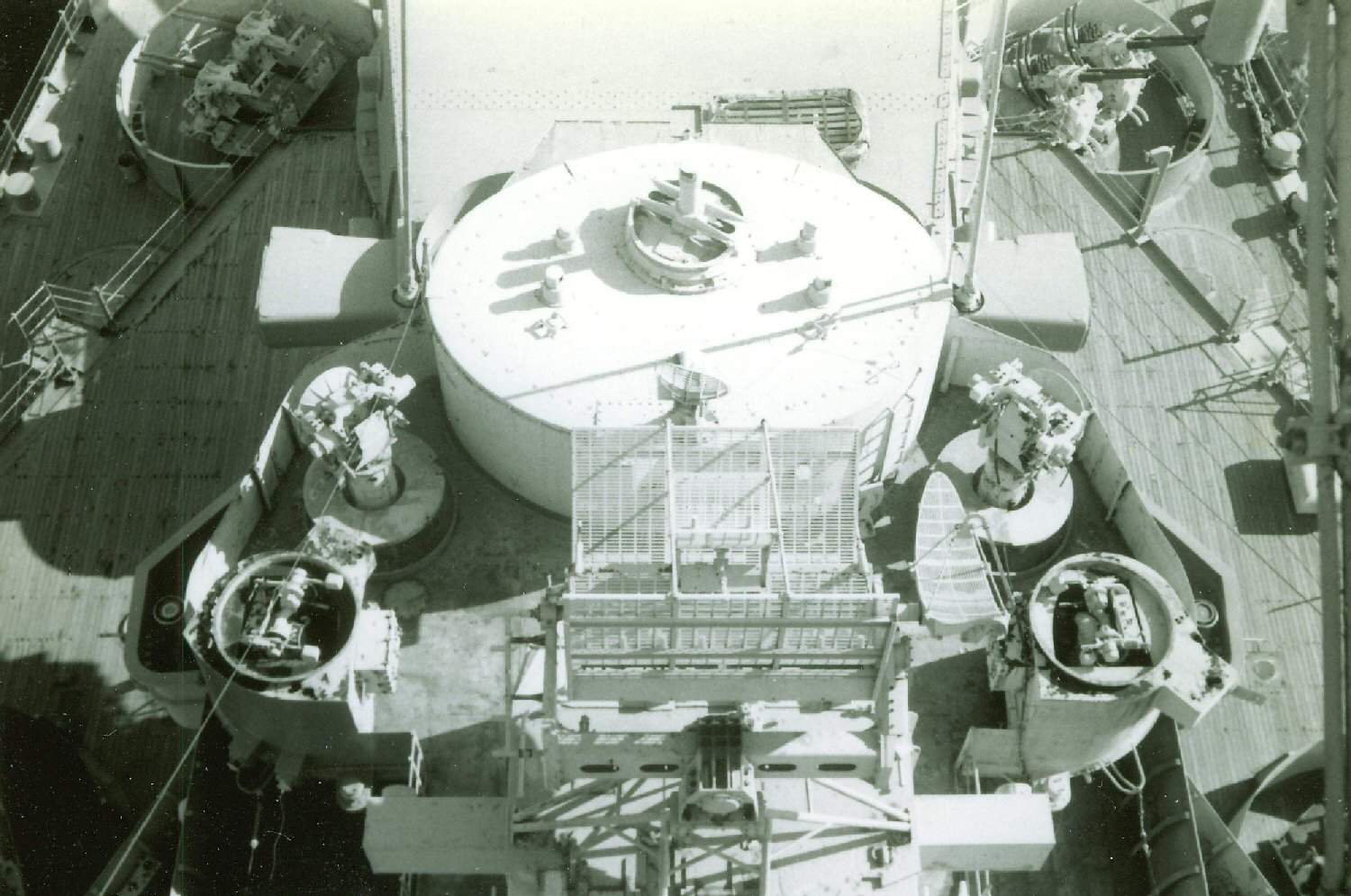
A conning tower, with center periscope for Mk 40 director (looking from above).
In extremis, the turrets could fire under local control. All three turrets were completed with 46-ft baseline rangefinders, although the rangefinder in Turret I was removed as it tended to get blinded by spray, and improved radar had rendered it less useful. There are sighting hoods on the sides of each turret for one trainer and three pointers (each gun elevates individually and has its own pointer), and a Mk 3 ballistic computer (without trunnion-tilt corrector).
There were also four Mk 37 directors for the 5” secondary battery, tied to Mk 1A computers paired in the forward and aft secondary battery plotting rooms. These are right next to the main battery plotting rooms, and there are suggestions that the directors can be cross-connected in some of my books. This may have had to be done manually, with cables passed through a porthole in the bulkhead between the two rooms. The Mk 37 was very similar in principle to the Mk 38, although it had to deal with targets in 3 dimensions. It was a fantastic system, which I’ll talk about later.
A Mk 37 director, circa WW2
One thing I haven’t mentioned is radar, with good reason. The system as originally designed did not have radar,6 although a few of the designers did know it was coming, and made sure that the directors had flat roofs. However, the second-generation Mk 8 radar had been installed on Iowa before she was even commissioned, giving full blind-fire capability. This was an early mechanically-scanned phased-array system, and it was replaced in the 1945 with the Mk 13 that is still on the ship today.
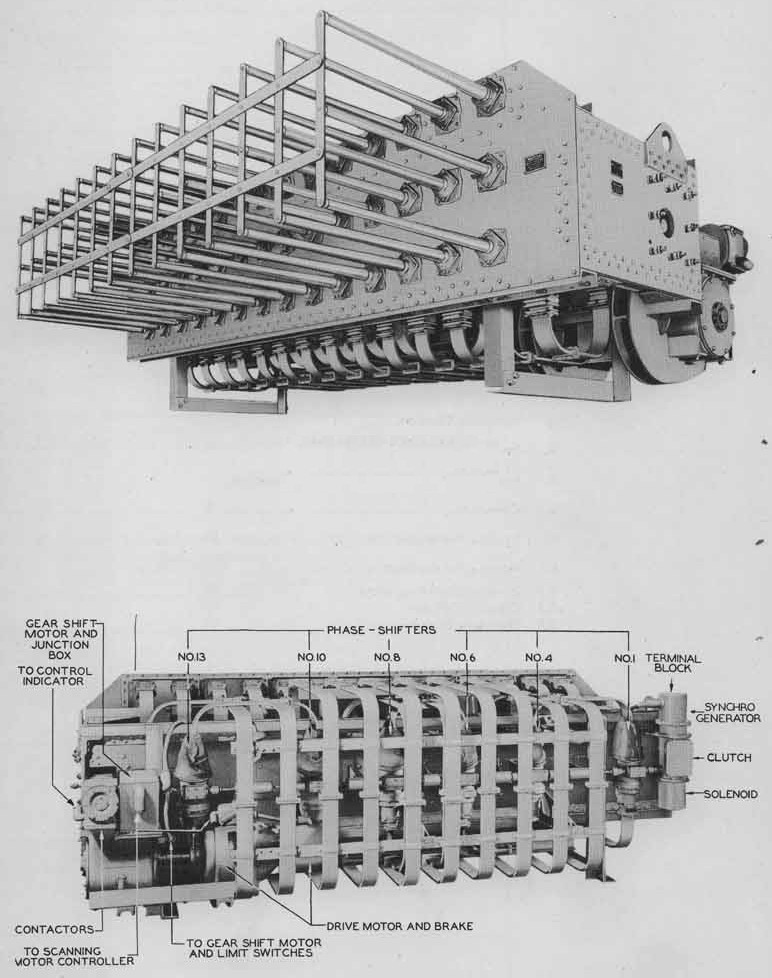
Mk 8 Radar
When the ships were reactivated in the 1980s, a pair of HP digital computers were added as adjuncts to the Mk 8s. These were used to provide a much better estimate of initial muzzle velocity and compensate for Earth’s curvature and rotation, trunnion height, target height, and wind, in the form of spots into the rangekeeper. The biggest problem was that the Mk 8s were limited to a fairly small range of muzzle velocities for the 1900 lb and 2700 lb shells, and any new shells had to be ballistically identical to one of these. The subcaliber shells under development would have required a different computer, and it was planned to replace the Mk 8s with the Mk 160 digital ballistic computer used on the Arleigh Burke class destroyer, although the ships were decommissioned before this happened. My source indicates this was only an issue of cams, and nothing to do with improving accuracy.
Iowa's fire-control system was by far the best in the world when it was introduced, and would have been a major advantage if she had ever gone into action against another battleship. Even though it never faced the ultimate test, it proved highly effective throughout her life, a testament to the men who designed it using slide rules.
Basic Fire Control Mechanisms (text)
Basic Fire Control Mechanisms (video)
Mathematical discussion of rangekeeping
Eugene Slover's website A great deal of excellent information, but somewhat poorly indexed and formatted. See here for some of the basic information on fire control.
1 Separate rangefinders have an irritating tendency to range on ships other than the one the director is looking at. ⇑
2 Author's photo. ⇑
3 Sadly, compensating for changes in enemy course or speed was still rather difficult. ⇑
4 This is actually a fuse-setting cam for a Mk 1A Computer, part of the Mk 37 (secondary battery) system. It's a rather odd object, as it was from the USS Nevada, and apparently is a cam designed for setting powder fuses, which were obsolete by the time Nevada got the Mk 1A. Still an amazing object. Author's photo. ⇑
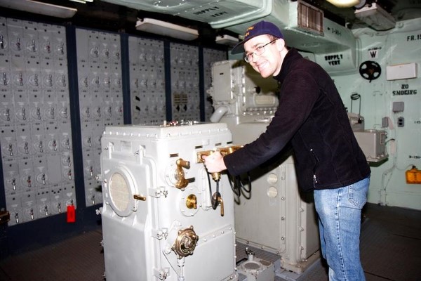
5 This is actually one of the secondary battery stable verticals. Behind me is the Mk 1A Computer. Not sure why the photo was taken here and not at the main battery stable vertical. Photo Courtesy of The Fatherly One ⇑
6 In fact, optical bearing information remained more accurate than radar bearings even in the 80s, and the preferred setup was optical bearing, radar range. ⇑
This post is an update of a post first made on SSC.
Comments
Correct me if I'm wrong, but one thing I'm getting from this is that a WWII-era system was still quite adequate ~40 years later. In general, I get the sense that warships are among the longest-lasting pieces of military hardware, but I would have expected that systems like this would be replaced much more commonly than the (expensive) ships themselves. Is this just a case of "did it right the first time" or is there something else going on?
They didn't get it right the first time. The system described here was the result of four decades of development, and those earlier systems were replaced on ships left over from WWI. I think the persistence of the WWII FC systems was basically a case of them being good enough for their job, and it not being worth the cost of replacing them. After the 40s, the Iowas weren't really in a surface-combat role, so the only major improvement was the shore bombardment computer/plot (which Wisconsin stole from our aft plot, and is poorly described in my books). The same goes for the other >5" guns. So any replacement wouldn't have given enough advantage to be worth the cost. Upgrades did happen throughout their lives, most notably the radar but also the digital computers in the 80s.
These days, that kind of minor upgrading of the hardware is pretty standard. One of the big changes in the 50s was that the cost of the combat systems went up a lot relative to basic hull cost. There have been serious proposals to stop doing mid-life upgrades and just put the new combat systems in new hulls for basically the same money. Of course, these were British proposals, so I think they ended up without new hulls or proper mid-life upgrades. But it does make very little sense to modify ships with big systems changes, like installing AEGIS on a non-AEGIS ship. They'll upgrade the software and maybe fit a new gadget or two, but you're generally better off with a new ship.