
While we’ve examined the history of battleship propulsion, from the dawn of steam through turbines and oil and the introduction of gearing, it’s now time to examine the pinnacle of the art, the plant built for the Iowa class. Going into (possibly excessive) depth on this system will make it a lot easier to understand the nuts and bolts of steam propulsion, as well as giving me a chance to showcase a part of Iowa very few visitors get to see.
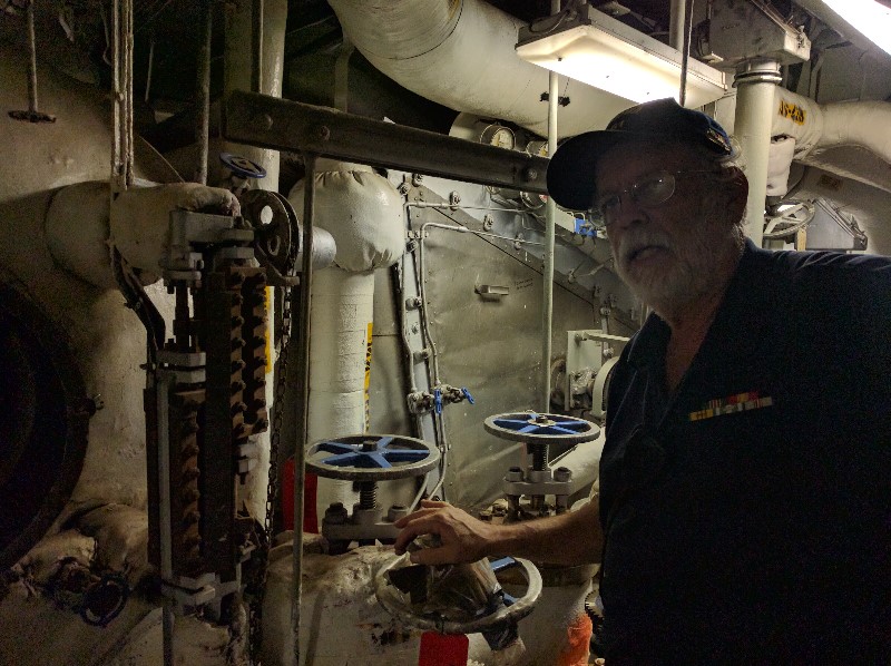
Jim Pobog explaining the boiler control system1
To propel the 53,900 tons of battleship at 32.5 kts required 212,000 HP, produced by 4,444 tons of machinery.2 Iowa’s machinery is arranged in four boiler rooms and four engine rooms, alternating in the space between Turrets II and III. Each boiler room contains two Babcock & Wilcox M-type water-tube boilers producing steam at 600 psi and 850 F. It can be divided into waterside and fireside, and we’ll look at waterside first. The feedwater enters the boiler and first passes through the economizer, which is a heat exchanger in the boiler exhaust, to get as much heat out of the exhaust gasses as possible. It then goes into the steam drum at the top of the boiler. From there, the downcomers route it into the water drums at the bottom, where it enters the steam tubes that take it back to the steam drum. It is in these tubes that most of the steam is generated. As it leaves the steam tubes, the mix of steam and water is at about 485°F, and moisture separators return any remaining liquid water to the steam drum. The steam goes into the superheater, where it is heated to the final temperature of 850°F and sent to the turbines. The water level in the plant is controlled manually. A boiler technician, universally known as a BT, was stationed near the steam drum. His job was to make sure that the water didn’t get too high and flow over into the turbines, or too low, which would make the boiler melt.
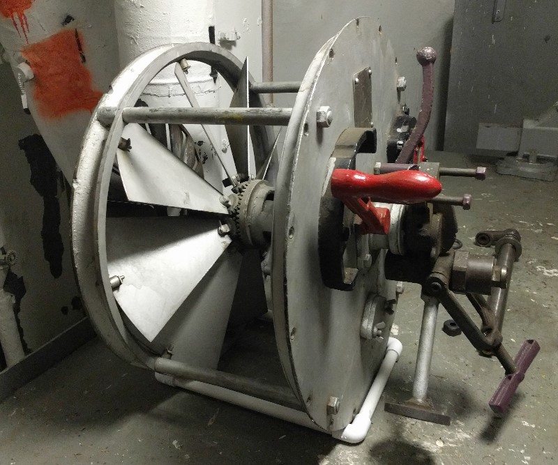
An air register
The heat for all of this comes from the oil burners on the fireside, five to evaporate the feedwater and four to superheat the resulting steam. Obviously, fire requires both air and fuel. The fuel comes through the atomizer. This uses steam to blow the fuel into a fine cloud. To control the amount of heat going into the fire, the BTs would bring burners online or take them offline. To get more precise control, the atomizer plate could be swapped out for one with a bigger or smaller orifice, which then let more or less oil through. The atomizer plate was installed in a device known as a gooseneck, which went through the center of the air register, a device that allowed the operator to control the flow of air into the furnace. Ideal combustion would produce little smoke, and a special periscope allowed them to view a lightbulb across the boiler exhaust. If the lightbulb wasn’t visible, the air registers would be adjusted to get the appropriate ratio.
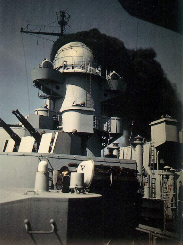
Soot being blown from the stacks on Iowa’s trials
Even though fuel oil burns much cleaner than coal, soot would still build up on the boiler tubes and impede heat transfer. To mitigate this, soot blowers were installed. These sprayed steam over the boiler tubes, removing the soot. The resulting plume of soot was very dirty, and captains were careful not to blow their boiler tubes when anyone was downwind. Unless, of course, someone you didn’t like very much was following you around. This was common during the Cold War.
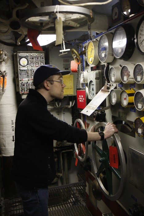
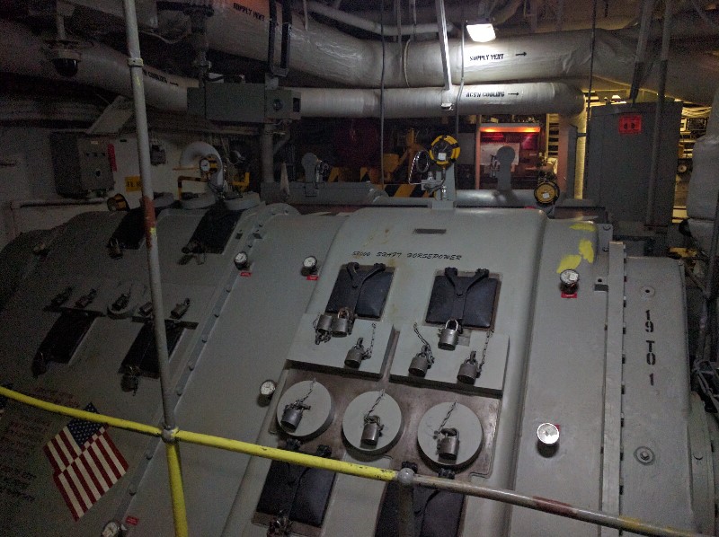
Me at the throttle board in Engine 23
The steam is routed from the superheater into the transfer piping that will take it to the turbines. Any boiler can provide steam to any turbine, and for maximum economy, Iowa sometimes steamed on as few as two of her eight boilers. However, it takes an hour or so to bring up a cold boiler, and it was normal to steam on four boilers, and all eight would be brought online when full speed might be required.
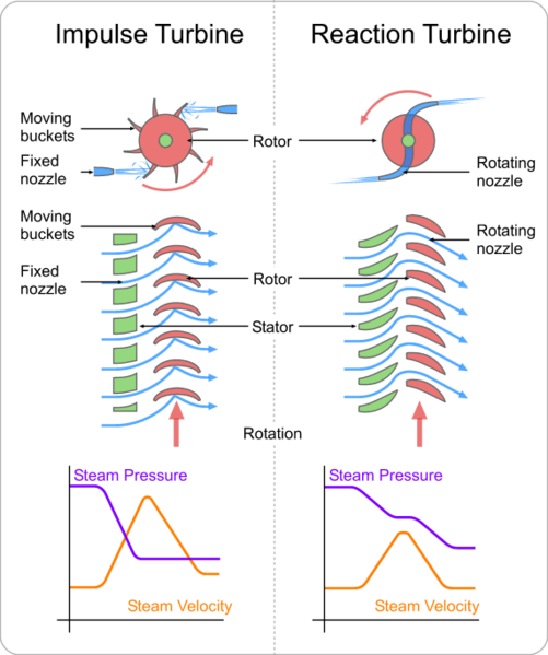
Each engine room contains a paired set of General Electric high and low pressure turbines. The steam first enters the high-pressure turbine, turning at 4,905 rpm at full power, with one row of impulse blades and eleven of reaction blades.4 The maximum power output of this turbine is 24,400 hp. The steam then enters the low-pressure turbine, which has six rows of reaction blades, and produces 28,600 hp at 3,913 rpm. The outputs of these turbines are geared together at 24.284:1 and 19.369:1 respectively using a double-reduction gear. This means that the power is stepped down in two stages, because a single stage would require infeasibly large gears. The reduction gearing is kept in a locked casing, as a popular way to sabotage a ship is to drop a wrench or other heavy object into the gearing.5 At full power, each shaft is turning at 202 rpm and passing about 53,000 HP to the screw, although the machinery was designed to accommodate a 20% overload.6 Inside the low-pressure turbine casing, there are two sets of astern blading with three blades each, totaling 11,000 hp. Despite their raw power, turbines are precision machinery. For instance, there’s an electric motor fitted to each to keep it turning after the steam is shut off so it doesn’t warp.
Iowa’s reduction gear
Directly underneath the low-pressure turbine is the condenser. The steam plant is at its core a heat engine, and that means that it has to get rid of heat somehow. This is dumped into seawater, which passes through a series of tubes inside the condenser, turning steam into water. Because all of the air is evacuated, the pressure inside the condenser is somewhere between 12 and 14 psi below atmospheric pressure, depending on the conditions. A ship in cold northern waters can generate more vacuum than a ship in the tropics, and consequently more power.
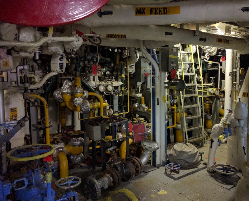
A small sample of the piping in Boiler 4
The condensate is then pumped into the deaerating feed tank (DFT), back in the boiler room. The DFT is intended to remove any oxygen dissolved in the condensate, to reduce boiler corrosion. This involves keeping it heated to just below boiling point and spraying it in a fine mist. This converts it to feedwater, and it’s then pumped back into the boilers, starting the cycle again.
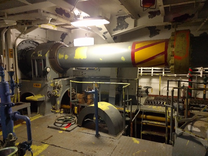
Shaft one in boiler room 4
Because the shafts originate in different engine rooms, each one is of a different length. From starboard to port, shaft 1 is 340′, shaft 2 is 243′, shaft 3 is 179′, and shaft 4 is 277′. The propellers on shafts 2 and 3 are five-bladed units 17′ in diameter, while the outboard shafts have 18′3″ four-bladed screws.
The ships originally burned black bunker oil. This was so thick that it required steam heating units in the fuel tanks to make it flow, and even then, it had the consistency of molasses. During the reactivation in the 80s, these were removed, the entire fuel system thoroughly cleaned and resealed, and the ships converted to burn Distillate Fuel, Marine, usually known as DFM. DFM is akin to diesel or jet fuel, and was the standard fuel for the USN. Modifying Iowa to burn it meant that she could be resupplied by the oilers, and could resupply escorting destroyers, too.
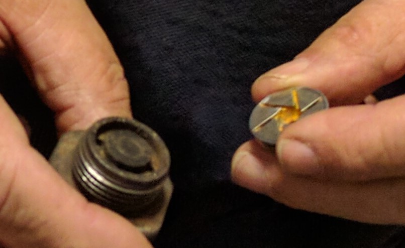
A close-up of one of the atomizers
Iowa’s design capacity of 8,642 tons of fuel oil allowed her to make 18,000 nm at 12 kts, 15,900 nm at 17 kts and 5,300 nm at 29.6 kts. As an example of how far naval engineering had come, at full power Warrior burned 3.75 to 5 lbs of coal/hp/hr. This fell to between 1.32 and 1.76 lbs/hp/hr in Dreadnought and as low as .66 lbs/hp/hr in Iowa, although in fairness the transition to oil, with its greater heat per unit weight, had a lot to do with that.
I think this concludes our tour of naval engineering for the moment. Iowa stands as the pinnacle of battleship engineering, and her engineering spaces have recently been opened to the public by the Full Steam Ahead Tour. I’d encourage anyone who can to go. If you can’t make it there, the Iowa app/audio tour thing has videos, and can be used anywhere. Search Battleship Iowa in the app or play store. There’s also a rather long video here with Jim Pobog, the tour lead. And I’ve posted more pictures of the boiler and engine rooms, along with some additional commentary. And if you’re interested in where things went later, I’ve covered naval propulsion since WWII with diesels, gas turbines, combination plants and nuclear plants.
If you want more technical information, I cannot recommend the book Introduction to Naval Engineering highly enough. It’s a fantastic practical thermodynamics text, and has an amazingly detailed account of slightly later 1200 psi steam plants.
1 All photos from my collection unless mentioned otherwise, or obvious. ⇑
2 This is 75% more HP/ton than was produced by Hood. See here for a discussion of ship power requirements. ⇑
3 Photo courtesy of the Fatherly One. ⇑
4 Impulse blades are turned by being pushed on by the steam, while reaction blades deflect the steam to get their push. ⇑
Comments
So all of this steam tech sounds really complicated and energetic, meaning that when things go wrong, body-parts tend to go missing rather too quickly. Was working on the power-plant among the desirable and prestigious jobs for sailors, or were those assigned to do so the poor devils of the ship?
Depends on who you ask. If you ask the snipes (engineering crew) themselves, they’re the elite. If you ask the deck apes (sailors who do the gruntwork above decks), the snipes are the poor devils.
In terms of actual danger, at least on Iowa (US plants in general, actually) it probably wasn’t any more dangerous than most jobs on the ship. If something goes wrong while you’re at the throttle board, you’re dead (it’s about 50 ft to the exit, and not a straight line) but that sort of thing was very rare with the 600 psi plants. And the guys on deck are taking substantial risks, too. Being crushed by a shell that got loose during UNREP isn’t really that preferable to being cut in half by a steam leak.
We might also note that the engine machinery was deep inside the ship and heavily armored, so you were unlikely to risk combat damage. (Sure, if the ship sank rapidly, life was hard, but mere 500-lb bombs or torpedoes were unlikely to affect anyone in the engine rooms until the ship was already in a very bad position.)
The air intakes for the boilers were built into the funnels, right? Not many people discuss that, and I only found one vague mention in a handbook.
Makes sense to limit the number of thermal exhaust ports some lucky religious fanatic could drop a 500lb photon torpedo down.
Yes. They’re actually visible on the tour, up on the 04 level, but they’re hidden behind some structure from external photographs.
Sorry, should be 03 level, not 04. It’s been a while since I was there.
This is getting way into the weeds, but does that overcompensate for the increase in viscosity of colder water? Or is form drag the dominant issue and not as much viscous / surface drag?
Did weather conditions (roll/pitch) impose additional limits on this, or was it sufficiently baffled that it was purely a level issue and you would have much bigger problems on your hands if roll became a problem?
Sorry, I realize this is getting way into the arcana of it, but it’s interesting!
All evidence points to cold water being a net advantage. Haven’t heard anything about changes in water viscosity messing with maximum speed much, so I don’t know if it’s just a low percentage change or wrong kind of drag offhand. As for roll, never heard of that being an issue, but I’m not a BT. Pitch is unlikely because it tends to have a longer period and lower magnitude than roll.
@Echo: the plans show them splitting up above the armored deck, implying 16 separate openings in the armor (that together are ~1% of the deck area), so that’s not the reason. Possibly they’re high up to avoid spray/waves???
Hi. Just found this by chance. It was weird to see my face suddenly pop up...
Hope you liked the tour.
HI. A very detailed question, can’t find an answer anywhere else. Trying to understand boiler, turbine, screw connections. In a normal configuration, are boilers 1 and 2 connected to turbine 1 and screw 1 (outer starboard)? B3 and B4 to T2 and screw 4 (outer port)? B5 and B6 to T3 and screw 2 (inner starboard)? B7 and B8 to T4 and screw 3 (inner port)? And how can they be cross connected? Finally, is this the same layout for the North Carolina and South Dakota class? Or please, point me to where I might find the answer. Thx john
Turbines obviously can’t be cross-connected across shafts, and your list of which set of turbines drives which shaft is correct per Sumrall’s Iowa Class Battleships. Boilers can be cross-connected, although apparently only within the forward group (boiler 1&2 and engine 1&2) and the aft group (boiler 3&4 and engine 3&4). (Learn something new every day.) North Carolina and SoDak both had only four boilers, each sharing the room with a turbine, although I’m pretty sure they had some cross-connection capability so they could run on only two boilers for cruise. Dulin & Garzke’s US Battleships confirms that the shaft/machinery room pairings are the same for those two classes.
I’ve been very fortunate to see one engine room in the New Jersey. do you know the weights of the major engine components? I’m guessing the reduction gear is the heaviest piece, wouldn’t be surprised if it outweighed both turbines combined.
Love this page!
I’m not sure I have that information available, and would need to think about the relative weights of the components. The turbines are bigger, but likely somewhat less dense. I may be able to get pictures of an open gear soon, as Wisconsin apparently has theirs open, which should help.
?? The turbines are shown as smaller than the gearbox in the drawings and photos I can find, though those also hint that their densities might be closer than the solid metal gears and mostly-steam-space turbines one might naively imagine.
I do have actual numbers for the electric alternative, but for a smaller and older system.
In the actual engine room, the turbines certainly look bigger, but it’s a pretty cramped space, and I wasn’t taking measurements. (You should come next year, by the way.) The turbines themselves are denser than you might think, and there’s also the condenser below the LP turbines, which arguably counts as part of them. As I said, not sure one way or the other.
As a plankowner from the 84 reactivation, I was thrilled to find this site. I worked EM01 )#1engine room) but the equipment is the same except we.had no shafts in our space to always have to crossover. Gave us a little more room it seemed. Anyway I was able to show the pics to family and show them what we did back then. Tjanks!
Glad I could help.
I’m used to thinking of steam engines as mostly boiler, but on ships that doesn’t actually seem to have been most of the weight. (Of the machinery itself; it does seem to have been the majority of the space, and the armor around the machinery spaces weighs about as much as the actual machinery.) Friedman says 691 tons of boilers out of 2452 tons total machinery on an original (coal-burning) New York, 337 and 532 tons on Oklahoma and Nevada (oil-burning; unsure which is which), and 245 tons after their 1920s refit.
I’m building my 3rd model for display in the USS New Jersey BB62. The first two: a full 16″ turret system in 1:72 and a 5″38 full gun system in 1:48. This one is Engine Room #3 (also in 1:48). I’ve got the condenser designed and am 3D printing it. I have full engineering drawings of most of the systems, but need more information about the main reduction gears. I’m making cutaways of all the major equipment. What are the diameters of the reduction gears: first pinion, 1st reduction, 2nd pinion and bull gear. I have fully dimensioned details of the MRG housing, but not of the gearing.
That sounds very cool. I’ll check some books later, but I would be very surprised if Ryan Szimanski doesn’t have everything I do on the Iowas, and then some.
regarding ships speed: in 1984 IOWA attained the speed of 36.6 kts. This piece of data was confirmed to me in May 2023 by our (IOWA’s) Commissioning Chief Engineer(“dont call me Cheng”), Cmdr. William G. Earnest USN. Nothing was recorded regarding the event, however, taking into consideration Cmdr. Earnest’s character and credentials (he’s a “Mustang”), he started his Naval career as an Engineman Fireman Apprentice (ENFA) and went up through the ranks..E2 to E9; W1 to W4; O2 to O6, retiring as a full Captain......I have absolutely NO reason to doubt his word....regardless of what other Battleship “Guru’s” say.....They never sailed with him..I DID !! I served 25 years in the Navy, retiring as a Chief Electricians Mate. During the course of my career I’ve served under no less than 8 Chief Engineers....he is/was bar none, by far the best Engineer I know, and I would sail with him anytime, anywhere, and under any circumstances.
Martin “Marty” Anthony Palmiere EMC(SW) USN(ret.) 1975-1999 USS IOWA BB-61 1983-1989.
John Nichols: Your describing the Engine Room/Main Engine/Shaft & Screw correlation is pretty much spot on except you label the turbines (T2) according to the ER they’re in when they should be labeled according to their associated shafts and screws. for example: Boilers # 3 & 4 in FR #2 feed #4 Main Engine(turbines, reduction gear and condenser = Main Engine)in #2 ER. We created a “jingle” to make it a little easier, goes like this: “One’s in One; Two’s in Three; Three’s in Four; and Four’s in Two” 1ME is in 1ER; 2ME is in 3ER; 3ME is in 4ER & 4ME is in 2ER (ME=Main Engine; ER= Engine Room; FR= Fire Room)
Hope I cleared things up and not confused further.