
Steam first went to sea in the early years of the 19th century. At first, it was used by navies primarily to tow ships in and out of harbor, being immune to wind and resistant to tides, both serious problems for sailing ships. Later, steamships were used extensively for minor roles, such as dispatch boats. In the 1830s, the first steam warships were built, such as HMS Gorgon. However, the use of paddle wheels meant that they could only mount a limited broadside armament, so only small ships received them. Larger ships retained sail exclusively until the advent of the screw propeller. Besides clean broadsides, screws also allowed the engines to be entirely below the waterline, where they were protected from enemy fire.
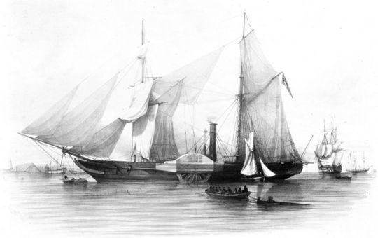
HMS Gorgon
The British and French began modifying existing warships, both frigates and line-of-battle ships, in the mid-1840s. The resulting "blockships" were intended to use their steam only sparingly, as the inefficient steam engines gave them only limited endurance. As the engines improved, so did the importance of steam in ship design, and by the time HMS Warrior was designed, her steam plant was as important as her sails. But before we examine them it more detail, we need to look at the basics of a steam plant.
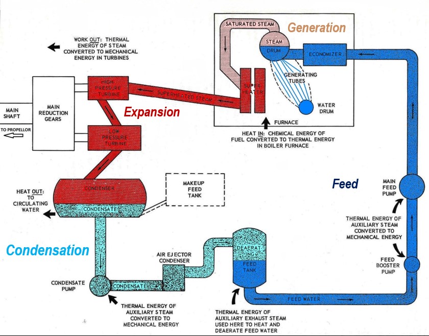
The basic steam cycle, as implemented on Iowa1
There are four main processes in the steam cycle: generation, expansion, condensation, and feed. Generation is where water under pressure is turned into steam by heating it up in a boiler. In the expansion phase, energy is taken out of the steam by the engines, lowering temperature and pressure. This is easiest to think of in terms of a simple reciprocating engine, where the steam pushes on the piston, but the same physics apply in a turbine. Condensation turns the steam back into a liquid, known as condensate. This creates a partial vacuum, which was actually the method by which the first steam engines worked, rather than using pressure above atmospheric. Finally, the condensate is pumped back into the boilers as feedwater.
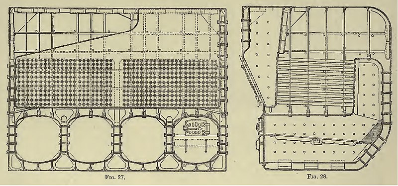
A box boiler
Warrior's steam plant was typical of the ships of the day. She had 10 box boilers, producing steam at about 22 psi. The boilers were coal-fired and fueled by stokers who shoveled the coal in by hand. The heating was done using fire tubes, the combustion gasses passing in many small tubes through the water that filled most of the boiler.
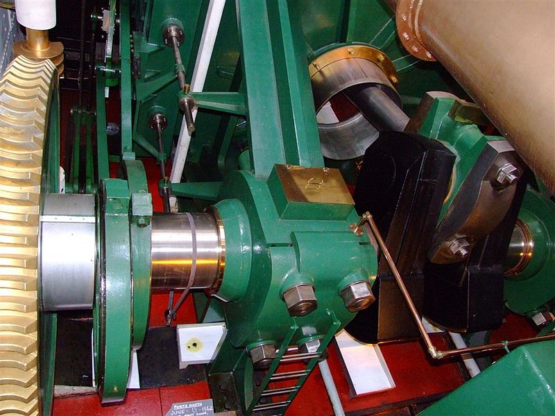
Warrior's trunk engine today
The engine was a two-cylinder trunk engine made by John Penn and Sons. The trunk engine was an ingenious method of giving high power in a relatively small package. The trunk was a hollow tube through the center of the cylinder, wide enough to give the connecting rod room to oscillate, and essentially cutting out the center of the cylinder. While this may seem bizarre, it allowed the connecting rod to be mounted at the cylinder head instead of behind it, giving a longer rod and smoother movement. The each cylinder had a diameter of 112.1"2 and a stroke of 48". The maximum speed was 56 rpm, and the whole setup produced about 5270 hp.
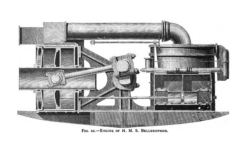
A diagram of a Trunk Engine
Once the steam had been expanded, a jet condenser was used to cool it. This sprayed seawater into a box on the opposite side of the crankshaft, cooling down the steam. This caused problems as the resulting mix of fresh and salt water was returned to the boilers. When water turns to steam, it leaves behind anything dissolved in it, so running a boiler on salt water makes it scale rapidly. In the 19th century, boilers had to be replaced every few years, an expensive and difficult job.
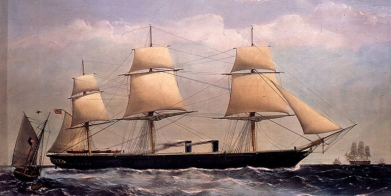
Warrior under way
Of course, the point of turning a shaft is to turn the propeller on the end. Warrior had a single screw 24'6" in diameter, coupled directly to the shaft. On trials she made as much as 14.3 knots, making her the fastest warship in the world at the time. However, early steam engines were very inefficient,3 and thus Warrior was also designed to perform well under sail. This included a mechanism that allowed the propeller to be disconnected from the shaft and hoisted up out of the water. The 35 tons of propeller and frame required 600 men to haul it up, and the funnel also retracted to reduce wind resistance. Needless to say, this was not a popular feature, and most later ships just had a fixed propeller.
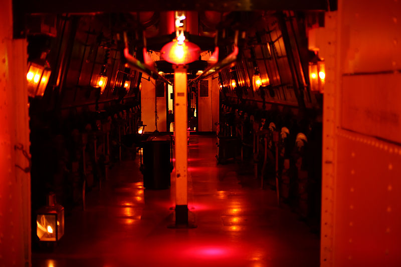
The boiler room on Warrior
Over the next few decades, sail declined in importance and then went away altogether, as engines became both more powerful and more efficient. The way this happened neatly illustrates the interlocking nature of progress. Warrior expanded her steam from the 22 psi all the way to near-zero in the course of a single stroke. This was inefficient and caused rapid wear from varying loads on the machinery. The obvious answer was to expand the steam multiple times in separate cylinders, but that was not particularly practical with the low steam pressures then in use. Higher steam pressure also meant that the machinery itself could be smaller. However, the boiler scaling problems got worse and worse at higher pressures, so the jet condensers were going to need to be replaced by a system that did not let salt into the feedwater.
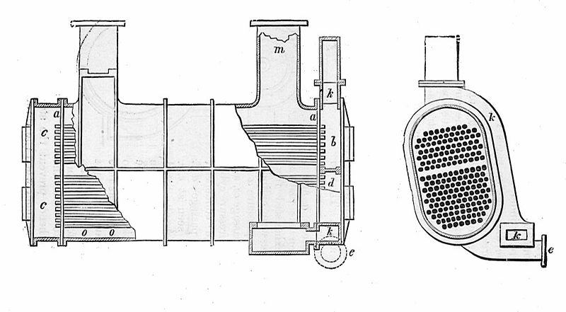
A surface condenser
Eventually, the surface condenser was developed. It worked rather like a boiler in reverse, passing the condensing steam through tubes in a box filled with seawater. Early efforts were thwarted by rapid corrosion of the tubes, a problem not fully solved until the 1930s. Improved metallurgy also allowed higher steam pressure, and in 1875, Dreadnought and Alexandra were fitted with the first compound engines aboard British battleships.4 On these ships, the engines were mounted vertically, as their thick belts were seen as sufficient protection against enemy fire. The engine on each of Alexandra's two shafts consisted of a 70" high-pressure cylinder exhausting into two 90" low-pressure cylinders, the whole assembly running on 60 psi steam produced by cylindrical boilers. The total installed power was 8,610 hp, and the ship was capable of 15.1 kts. On 680 tons of coal, she could steam 3,800 miles at 7.5 kts, although her performance under sail was poor at best, as steam had clearly become the dominant power source.
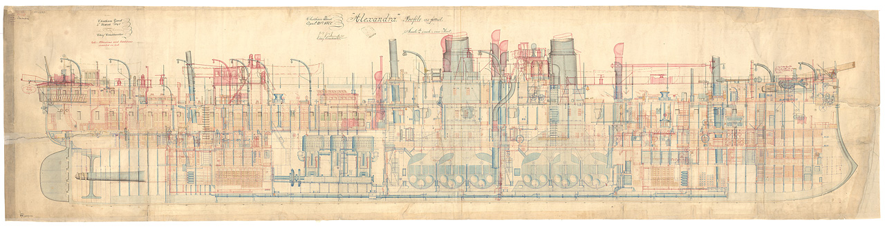
Cross-section of HMS Alexandra, with boilers and engines visible
The Admiral class introduced another innovation, forced draft.5 Instead of simply relying on the natural circulation of hot gasses through the boilers, air was forced into the boiler room by fans, allowing more coal to be burned in the boilers. At least in the early years, forced draft was only used when really high speed was needed, and it was not popular with crews, due to the extra effort and wear on the machinery, as well as the need to seal the stokehold. In the Admirals it was also mostly useless because the engines were not able to absorb the extra steam.
A Triple-expansion steam engine
The use of the compound engine allowed sails to be discarded, but even greater economy was desired. The triple-expansion engine was first used on HMS Victoria. In this engine, the steam was expanded three times, in cylinders of 42", 62", and 96". The total power of 7,500 hp under natural draft gave a speed of 15.3 kts, while forced draft could give 14,000 hp and 17.2 kts. Victoria carried 1,000 tons of coal, and could make 7,000 miles at 10 kts, a massive improvement over Alexandra.6
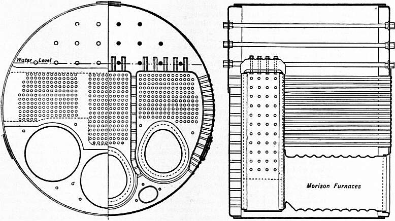
A Cylindrical boiler
In the 1890s, naval engineering continued to evolve rapidly, spurred on by the development of the torpedo boat, and then the destroyer. These small, fast vessels demanded ever-increasing levels of power and lower weight. As a result, they were almost always the first to introduce new innovations. However, this is ultimately a battleship blog, and so we'll focus on the improvements in naval engineering as applied to capital ships.
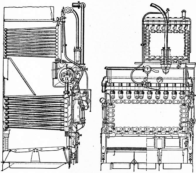
A Belleville boiler
The next innovation was the water-tube boiler. First introduced on the Canopus class, this reversed the position of the fire and water in the boilers. Water-tube boilers were lighter, could be throttled faster, and were smaller for the same power. The fact that the waterside was smaller meant that steam pressure could rise even more.7 However, the first water-tube boilers, the Bellevilles, proved difficult in service. This was a common problem with new and more sophisticated equipment, which was often operated by men used to older, simpler, and more forgiving gear. The resulting "Battle of the Boilers" saw other types, such as the Yarrow enter service.
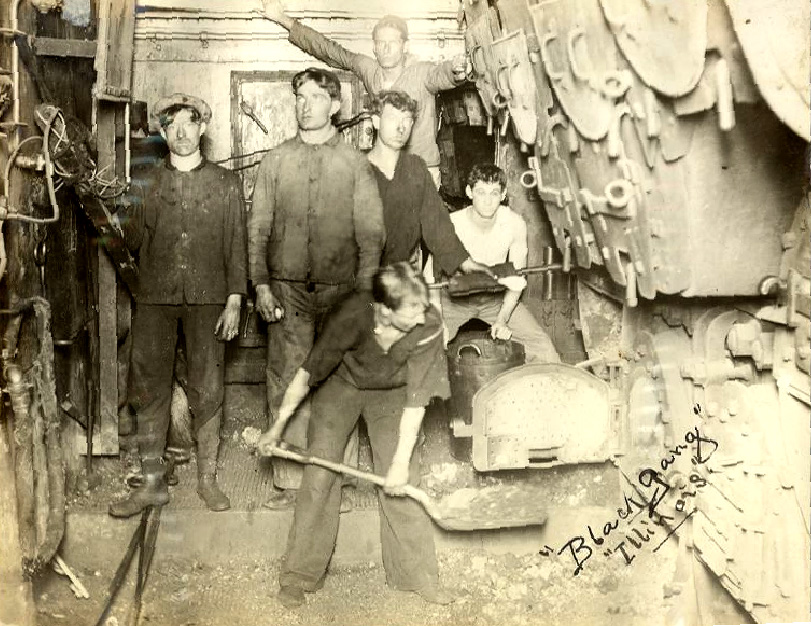
Boiler room of USS Illinois (BB-7)
The machinery spaces of a warship in the late 19th century were hellish. They were hot, extremely loud, dirty, and full of vibrating machinery. Steam leaks were a constant threat. The best way to search for a steam leak is with a piece of wood. When pieces start going missing, you've found the leak. The alternative is to notice when body parts are cut off by the high-pressure steam, which is considered a poor second for obvious reasons.
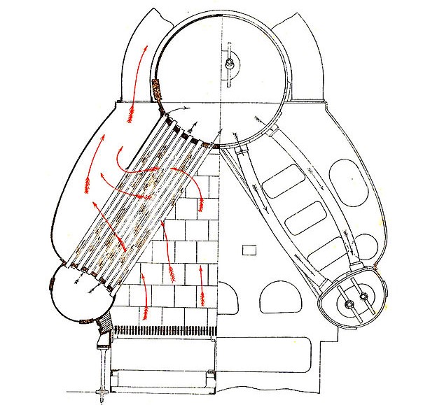
A Yarrow boiler, showing the steam tubes on the left and the downcomers8 on the right
The Canopus class had a total power of 13,500 hp propelling the ship at 18.25 kts from two sets of 3-cylinder triple expansion engines on two shafts, and 20 Belleville boilers operating at 300 psi. She could carry up to 1,800 tons of coal, although 900 tons was the normal value. This gave a range of 5,230 nm at 10 kts, and 2,590 nm at 16.5 kts.
All of the ships described here ran on coal and used reciprocating engines. Next time, we'll look at the dramatic change in the first decade and a half of the 20th century, when this setup was swept away and replaced by oil and turbines.
For more details on early marine engines, see this book.
1 Thanks to Jim Pobog for the diagram. ⇑
2 Once the trunk was subtracted, the effective diameter was 104.6". ⇑
3 Warrior burned about 3.5 to 5 lbs/hp/hr, and had a coal capacity of 850 tons. At 11 kts, she could steam about 2,100 nm. ⇑
4 As with my early design history, I'm sticking with British practice here due to source availability. ⇑
5 For some reason, the British insist on spelling this as "draught". I assume this is due to their weird "u" obsession. ⇑
6 Some later pre-dreadnoughts had four-cylinder triple-expansion engines, which had two low-pressure cylinders to avoid an impractically large single low-pressure cylinder. ⇑
7 The obvious question is why they weren't introduced sooner. David W at SSC has offered an excellent explanation. Basically, steel starts to lose strength at about 300°C, and coal and oil burn at 2000°C, so the steel has to be kept cool by the water. If a tube in a water-tube boiler goes dry for some reason, it softens or melts, then breaks, and the boiler loses pressure. A fire-tube boiler is guaranteed not to have that happen, because it's a big box of water with fire going through it. As they were able to avoid clogging and other mechanical issues, water-tube boilers became practical. ⇑
8 Tubes that return water from the steam drum (top) to the lower water drum ⇑
Comments
Fascinating stuff!
So with the blockships and later sail/steam hybrids, was it basically steam for combat, sail for transportation?
It varied. For the blockships, emphatically so. As the steam engines got more efficient, sails were less useful and received less design emphasis, so they got even less useful. Alexandra, for instance, was very good under steam but quite poor under sail. Sails lasted longest in cruisers intended for distant stations far away from coaling facilities. Battleships that would operate around bases got rid of them fairly quickly.